 English
 Español

NEWS
NEWS
NEWS
NEWS
NEWS
NEWS
NEWS
NEWS
NEWS
NEWS
NEWS
NEWS
NEWS
NEWS
NEWS
NEWS

Industry News
Home / News / Industry News / How Do You Measure the Dew Point? Instruments, Methods, and Lab Accuracy
How Do You Measure the Dew Point? Instruments, Methods, and Lab Accuracy
Content
- 1 What the Dew Point Number Actually Means
- 2 Direct Measurement: Cooling a Surface Until Moisture Appears
- 3 Deriving Dew Point From Temperature and Relative Humidity
- 4 Calibration and Field Checks That Catch Drift
- 5 Dew Point Control Inside a Humidity Test Chamber
- 6 Rapid Ramps and Cold Loads: Where the Margin Disappears
- 7 Below Zero: Frost Point and Cryogenic Sample Handling
- 8 Frequently Asked Questions
- 8.0.1 Q1: What is the simplest way to measure the dew point?
- 8.0.2 Q2: How accurate is a calculated dew point?
- 8.0.3 Q3: Why does a chamber show condensation when humidity is on target?
- 8.0.4 Q4: Does the same instrument work on compressed air?
- 8.0.5 Q5: How often should a dew point instrument be calibrated?
A damp-heat soak sits at 40 °C and 93 %RH. Twenty minutes into the ramp that follows, the chamber air still holds enough water for a dew point near 39 °C. Anything in the working volume that is two degrees cooler than that collects liquid water, whatever the humidity display says.
Dew point is measured two ways. A direct instrument cools a surface until moisture condenses on it and reports that temperature. An indirect method measures dry-bulb temperature and relative humidity, then converts the pair with a vapor-pressure equation. Direct instruments hold the tighter tolerance and cost more; calculated values are fast, cheap, and only as good as the humidity sensor behind them.
Which route you need depends on the job: a reference value in a calibration chain, a logged variable in a chamber test, or a quick check on a duct. The sections below cover how each method works, the tolerance to expect, and the places where a reading quietly goes wrong.
What the Dew Point Number Actually Means
Dew point is the temperature to which air must be cooled, at constant pressure and unchanged moisture content, before it becomes saturated. Because moisture content does not change as air is warmed or cooled in a closed space, dew point stays almost fixed while dry-bulb temperature moves, which is why it is often the more informative value in a test chamber.
Relative humidity is a ratio rather than a quantity. A chamber at 20 °C and 50 %RH and one at 40 °C and 50 %RH show the same display value but hold very different amounts of water: their dew points are about 9 °C and 28 °C.
Below 0 °C the reference changes. Moisture deposits as ice, and saturation over ice sits below saturation over water, so the frost point reads higher than a dew point calculated over water at the same vapor pressure, by roughly 2 °C near -20 °C and more than 3 °C near -40 °C.
Direct Measurement: Cooling a Surface Until Moisture Appears
Direct instruments share one principle: bring a surface to the temperature at which a vapor-to-liquid or vapor-to-solid transition happens, then report that temperature. They differ in how the surface is cooled, how the film is detected, and how long they stay accurate in dirty air.
Reference gradeContinuous loggingTrace moistureField checks
- Chilled mirror. A cooled mirror held at the equilibrium point where a thin dew or frost film stays constant, detected optically. Typical accuracy is ±0.1 to ±0.2 °C, and it is the reference method; dust, oil mist and salts on the mirror shift the detection point.
- Capacitive polymer sensor. The element measures relative humidity, and the transmitter calculates dew point from that value plus a measured temperature. Small, quick and inexpensive, with gradual drift as the polymer ages.
- Aspirated psychrometer. Matched thermometers, one wetted, ventilated at about 3 to 5 m/s. Accuracy depends on aspiration, wick condition and water purity, commonly ±0.5 to ±1.0 °C.
- Lithium chloride dew cell. A salt solution between electrodes settles at an equilibrium temperature that tracks vapor pressure. Rugged for industrial ducts, but it needs cleaning and works poorly below about -30 °C.
- Aluminium oxide and spectroscopic analysers. Oxide sensors reach frost points near -100 °C at ±1 to ±2 °C; laser absorption and ring-down instruments resolve parts per billion and mainly certify calibration gases.
Which Method Fits Which Job
| Method | Typical dew or frost point range | Typical accuracy | Best suited to |
|---|---|---|---|
| Chilled mirror | -70 to +60 °C | ±0.1 to ±0.2 °C | Reference values, calibration chains |
| Capacitive sensor with calculation | -40 to +60 °C | ±0.3 to ±0.5 °C | Chamber and duct logging |
| Aspirated psychrometer | 0 to +60 °C | ±0.5 to ±1.0 °C | Field verification, training |
| Lithium chloride dew cell | -30 to +60 °C | around ±0.5 °C | Industrial dryers and ducts |
| Aluminium oxide sensor | down to -100 °C | ±1 to ±2 °C | Trace moisture in process gas |
In practice the choice narrows to a chilled mirror where the value must be traceable, and a capacitive transmitter where the value is a trend.
Deriving Dew Point From Temperature and Relative Humidity
If temperature and humidity are the only measurements available, dew point is a calculation away. The August-Roche-Magnus approximation stays within roughly 0.4 °C between -40 °C and +50 °C and fits into any spreadsheet.
γ = ln(RH / 100) + (17.625 × T) / (243.04 + T)
Td = (243.04 × γ) / (17.625 − γ)
At 25 °C and 50 %RH, γ works out to 0.9507 and the dew point to 13.9 °C, which matches published tables for the same pair.
Error amplification is the part that catches people out. A 1 %RH error moves the dew point by about 0.3 °C at 25 °C and 50 %RH, but by well over 1 °C at 10 %RH. A sensor rated ±3 %RH therefore supports a dew point figure of roughly ±1 °C in ordinary air and a much weaker one when the air is dry. Temperature error passes through almost unchanged, so the temperature channel deserves equal attention; worked Magnus formula examples show how the arithmetic behaves across the range.
0.3 °CDew point shift per 1 %RH at 25 °C and 50 %RH
above 1 °CShift per 1 %RH at 25 °C and 10 %RH
0.4 °CTypical formula error from -40 to +50 °C
Calibration and Field Checks That Catch Drift
Readings drift, and the drift is hard to notice because the output always looks plausible. Three checks cover most laboratory cases.
- Saturated salt solutions. At 25 °C, sealed jars of lithium chloride, magnesium chloride, sodium chloride, potassium chloride and potassium sulfate hold roughly 11 %, 33 %, 75 %, 84 % and 97 %RH. Two or three points reveal offset and slope, and ±2 to ±3 %RH is a reasonable window for a routine annual check.
- A reference instrument. A clean chilled mirror inside its calibration interval is the practical cross-check for capacitive sensors in a chamber or a duct.
- Contamination review. Solvent vapor, plasticiser, salt spray and condensation all leave a film on sensing elements, so after any such exposure treat the previous calibration as void.
Two details decide whether a reading is usable. The sensor must sit at the temperature and pressure of the air being judged, because a sensor near warm electronics reports the air around the board rather than the air around the sample. And dew point in a pressurized line is a pressure dew point: -40 °C at 7 bar is far drier in absolute terms than -40 °C at room pressure, so the two numbers cannot be compared without converting them.
Dew Point Control Inside a Humidity Test Chamber
In a climate chamber the controller really manages moisture content; relative humidity follows from dry-bulb temperature and dew point together. A tolerance of ±2 %RH converts to roughly ±0.5 °C of dew point near room temperature, and that conversion is worth doing before the figure goes into a test plan, because the acceptance criterion for many products is condensation rather than humidity.
Condensation appears whenever a surface falls below the dew point of the air around it. During a heating ramp the sample and its fixture lag behind the air, so the coldest objects set the risk. Logging dew point next to temperature and humidity makes that risk auditable after the run, and it usually explains water found on a connector at the end of an otherwise compliant test.
For cyclic damp-heat profiles that program temperature and humidity together, an alternating temperature and humidity chamber is the usual platform.
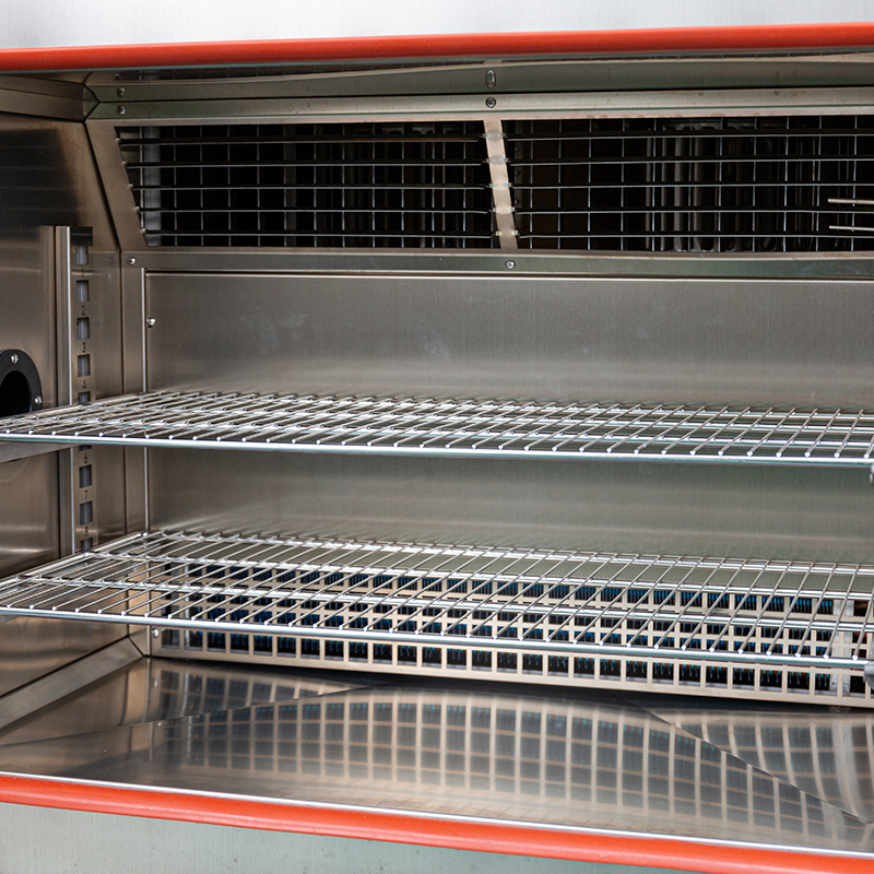 UTH-100-A Alternating Temperature and Humidity Test ChamberFor cyclic damp-heat profiles, this 100 L chamber pairs programmed temperature and humidity control with dynamic PID and water vapor partial pressure regulation.View Product →
Rapid Ramps and Cold Loads: Where the Margin Disappears
Fast temperature-change profiles make the heaviest demands on moisture control. Holding relative humidity through a rapid heating step means adding water vapor quickly; reaching a cold soak from a warm, humid state means removing it just as fast. A chamber that meets its setpoints at steady state can still overshoot dew point in transition, and the overshoot shows up as condensation on cold masses rather than as a deviation on the display.
Control that regulates dew point directly, and a documented dry-out phase before each cold step, both reduce the risk. So does knowing how the chamber behaves when a large cold load pulls air temperature down faster than the moisture loop can respond.
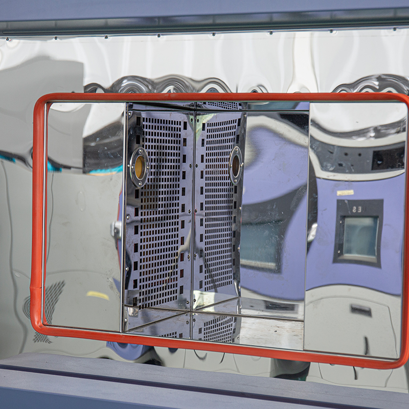 U5QTH-100-A/W Fast Temperature and Humidity Cycling ChamberRapid 100 L cycling chamber with optional 5–20 °C/min rates and balanced humidity control, suited to fast temperature and humidity test sequences.View Product →
Below Zero: Frost Point and Cryogenic Sample Handling
Below 0 °C the number to control is the frost point. In a freezer, a cryogenic store or a vacuum transfer chamber, any surface colder than the frost point of the surrounding gas grows ice, and one transfer at the wrong moisture level can leave a frost layer that only shows up later under a microscope. Keep the purge gas or vacuum space at least 5 °C drier than the coldest surface in the transfer path, and verify that margin with an instrument calibrated at the low end rather than at room temperature.
 CVC100 Vacuum Cryogenic Sample Transfer ChamberA vacuum transfer chamber with liquid nitrogen cooling trap and touchscreen valve control, helping reduce frost and moisture contamination of frozen samples.View Product →
Frequently Asked Questions
Q1: What is the simplest way to measure the dew point?
A calibrated temperature and relative humidity meter plus the Magnus calculation. That is adequate for monitoring and trend work; where the number has to stand as a reference value, use an aspirated psychrometer at minimum and a chilled mirror where the tolerance allows.
Q2: How accurate is a calculated dew point?
Expect roughly ±0.5 °C from a good sensor near 25 °C and moderate humidity, and about ±1 °C or worse in dry air. Below roughly 15 %RH the calculation amplifies humidity error heavily, so a single wet calibration point does not validate dry-end performance.
Q3: Why does a chamber show condensation when humidity is on target?
Because the display describes the air while condensation depends on surface temperature. A metal fixture, cable or sample can sit a few degrees below the air's dew point while the sensor reads the setpoint. Compare the dew point with the coldest surface in the working volume, not with the humidity value.
Q4: Does the same instrument work on compressed air?
Only if it is rated for line pressure. The result is a pressure dew point that changes as the gas expands, so it cannot be compared directly with atmospheric values, and ambient-pressure sensors may be damaged by the flow.
Q5: How often should a dew point instrument be calibrated?
Twelve months is the common starting interval, shortened in dusty, oily or condensing environments and always repeated after exposure to solvents or a liquid water event. For damp-heat testing, compare humidity-capable environmental test chambers on how they control and log dew point, not only on the stated relative humidity tolerance.
Matching the method to the tolerance is the whole decision. A capacitive sensor and a spreadsheet formula answer most monitoring questions at low cost; where the number feeds a calibration chain, a qualification report or a frost-sensitive transfer, a chilled mirror or a traceable cross-check is usually cheaper than the retest.
Three habits make any method more dependable: record temperature, humidity and dew point together so the data can be audited later; verify the sensor under the conditions in which it will actually be used; and convert the criterion you care about, condensation on a surface, into a dew point margin before the test begins.
PREV:Environmental Simulation Testing: Chamber Selection, Specs and Test Standards
NEXT:Environmental Chamber Validation: A Practical Guide to Reliable Test Data
NEXT:Environmental Chamber Validation: A Practical Guide to Reliable Test Data
Interested in cooperation or have questions?
Featured Products
Related products
Quick Link
Contact Information
- Tel: +86-13861043568
- E-mail: 1840784112@qq.com
- Add: Tianting District, Changzhou City, Jiangsu Province, China, No. 6 Hecircuit
Scan Code
Copyright © JIANGSU BAISHENG INDUSTRIAL CO., LTD.
All Rights Reserved. Privacy Custom Precision Laboratory Testing Equipment Manufacturers
