 English
 Español

NEWS
NEWS
NEWS
NEWS
NEWS
NEWS
NEWS
NEWS
NEWS
NEWS
NEWS
NEWS
NEWS
NEWS
NEWS
NEWS

Industry News
Home / News / Industry News / Environmental Chamber Temperature Humidity Control: Specs and Selection Guide
Environmental Chamber Temperature Humidity Control: Specs and Selection Guide
Content
- 1 How an Environmental Chamber Controls Temperature and Humidity
- 2 Control Specifications That Determine Test Validity
- 3 Why Temperature and Humidity Control Belongs Together
- 4 Standards That Depend on Combined Temperature and Humidity Control
- 5 How to Select a Chamber That Holds Your Profile
- 6 Frequently Asked Questions
Put a batch of lithium-ion cells into a chamber, program 85°C and 85% RH, and walk away for 500 hours. Whether that test produces trustworthy data depends less on the nameplate and more on how precisely the chamber holds both temperature and humidity at every stage of the run. Environmental chamber temperature humidity control is too often treated as a brochure line, yet it determines whether a profile stays inside tolerance, whether condensation lands on the specimen, and whether a two-week test has to be restarted. This guide explains how chamber control works, which specifications actually matter, and how to match a chamber to the profiles you really run.
How an Environmental Chamber Controls Temperature and Humidity
An environmental chamber is a closed-loop system with one job: to keep a volume of air at the temperature and moisture condition you specify. The controller reads sensors inside the working volume, compares the readings with the setpoint, and adjusts heaters, refrigeration, and humidification or dehumidification outputs. A blower continuously circulates the conditioned air so the test load sees the same environment regardless of where it sits.
The control loop in practice
Most controllers use a PID algorithm. Proportional, integral, and derivative terms respond to how far the chamber is from setpoint, how long the error has persisted, and how quickly the error is changing. A properly tuned loop holds temperature within ±0.5°C and relative humidity within ±2% RH during steady-state dwells. A poorly tuned loop overshoots on heat-up, oscillates around the setpoint, and produces results that are hard to repeat. When you evaluate a chamber, ask how the controller behaves during ramped and cyclic profiles, not only in steady state.
Where humidity control gets complicated
Humidity starts with temperature. A steam generator or ultrasonic humidifier adds moisture into the air stream; a chilled coil or dry-air purge removes it. Every humidification step changes the heat balance of the chamber, and every dehumidification step cools the air. Humidity response is therefore slower and more coupled than temperature response, and that coupling is the root of most control problems in environmental testing.
- Resistive heaters in the air plenum provide the heat input.
- A cascade or single-stage refrigeration loop cools the air and supplies the chilled coil used for dehumidification.
- A steam generator adds moisture through purified water vapor.
- A blower distributes the conditioned air around the test load.
For combined cyclic profiles, a chamber such as the UTH100A alternating high-low temperature humidity chamber is designed to coordinate temperature and humidity loops in the same sequence.
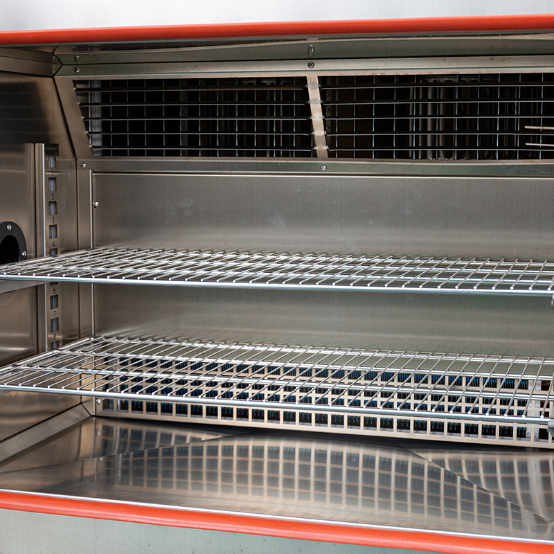 UTH-100-A Alternating Temperature and Humidity Test ChamberThis chamber coordinates temperature and humidity loops in combined cyclic profiles, making it suitable for tests that require simultaneous control. Its balanced PID system and durable stainless steel interior support precise and reliable operation.View Product →
Control Specifications That Determine Test Validity
No single specification defines environmental chamber temperature humidity control quality. You need a small set of numbers, each describing a different behavior of the system.
±0.5°CTypical temperature stability
±2% RHTypical humidity tolerance
10–15°C/minRapid-rate ramp options
The table below lists the control parameters that deserve verification before purchase. Each one changes the result of a real test.
| Specification | Typical Range | Practical Meaning |
|---|---|---|
| Temperature range | -70°C to +150°C | Limits the stress extremes you can apply |
| Temperature stability | ±0.3°C to ±0.5°C | Long-dwell accuracy at the setpoint |
| Temperature uniformity | ±1°C to ±2°C | Evenness of stress across the test load |
| Humidity range | 20% to 95% RH | Moisture window for damp-heat profiles |
| Humidity tolerance | ±2% to ±3% RH | Tightness around the RH setpoint |
| Ramp rate | 1°C/min to 15°C/min | Speed of thermal cycling profiles |
Uniformity deserves the closest attention because it is the most commonly misread specification. Chamber ratings are measured with an empty working volume. Add a dense battery pack or a loaded PCB stack, and airflow is disturbed enough to degrade uniformity by 50% or more. If your product fills a large part of the chamber, the relevant question is not whether the return-air sensor is in tolerance; it is whether the corner of the specimen experiences the same stress as its center.
Stability matters most in long-dwell tests. A chamber holding ±0.3°C produces a more consistent result than one drifting by ±1.5°C, particularly when every data point is later used to calculate activation energy, lifetime, or a safety margin.
Why Temperature and Humidity Control Belongs Together
Relative humidity is a ratio, not an absolute quantity. It compares the water vapor actually present in the air with the maximum vapor that same air can hold at its current temperature. Because the denominator changes with temperature, any temperature error immediately becomes a humidity error. At 85°C, a temperature drop of barely more than 1°C can push the air to saturation. This is why temperature and humidity must be treated as one integrated control problem rather than two independent features.
Three operating zones cause most field problems
- High temperature with high humidity. The humidifier operates against hot air, and if the generator is undersized, RH recovery after loading takes far too long.
- High humidity to low humidity transitions. Dehumidification needs a coil cold enough to condense water, after which the air must be reheated. The transition is inherently slow and energy-intensive.
- Low temperature with low humidity. Cold air holds very little vapor. Profiles that demand low RH at sub-zero temperatures are physically impossible with a standard single-stage chamber.
Design tipRequest the psychrometric operating envelope from the manufacturer before you fix a profile. A chamber rated at 20% to 95% RH cannot necessarily reach every humidity setpoint at every temperature.
The practical effect shows up in moisture-resistance analysis, where a slightly loose humidity loop can switch a product from pass to fail. For a closer look at the mechanism, see how precision humidity control chambers redefine moisture-resistance analysis.
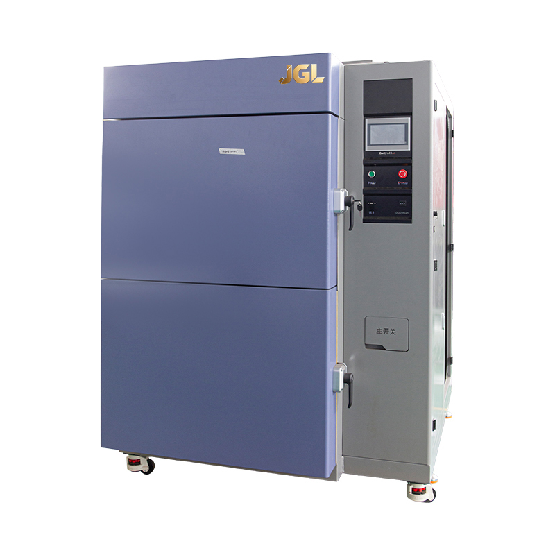
For alternating temperature and humidity phases, a cycling chamber such as the UTH150A high-low temperature humidity cycling chamber coordinates both loops, which keeps transition behavior under control.
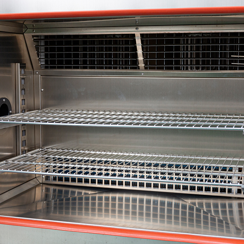 UTH-150-A Temperature and Humidity Cycling ChamberDesigned for cycling temperature and humidity phases, this chamber maintains accurate conditions needed for standards that demand simultaneous control. It offers high-precision regulation, safety protections, and energy-efficient operation for extended testing.View Product →
Standards That Depend on Combined Temperature and Humidity Control
A number of standards would be meaningless without simultaneous temperature and humidity control:
- IEC 60068-2-78: damp heat, steady state, typically 85°C/85% RH for hundreds or thousands of hours.
- IEC 60068-2-38: combined temperature/humidity cyclic tests with alternating heat, humidity, and cold phases.
- MIL-STD-810 humidity methods: procedures that emphasize condensation and drying cycles on operational equipment.
- JESD22-A110: highly accelerated temperature and humidity stress testing (HAST) for semiconductor packages.
- ISO 16750-4: combined temperature and humidity loads for automotive electrical and electronic hardware.
What these standards share is a profile-based control requirement. Setpoints have to be reached within defined tolerances, held without drift, and cycled within limited transition times. The hardest part is rarely the steady-state hour at 40°C and 93% RH; it is the transition into and out of that phase, when the specimen generates its own heat and the chamber must simultaneously change temperature and manage humidity without forming condensation.
How to Select a Chamber That Holds Your Profile
Selection should begin with the test profiles, not with the brochure. Write down the setpoints, ramp rates, dwell times, and tolerances of every standard you plan to run, and then check these five points:
- Working volume and load density. Keep at least 20% free air space around the test load. Blocked airflow degrades both temperature uniformity and humidity distribution.
- Real uniformity at your test points. Ask for measured uniformity data at the temperatures and humidity levels in your profiles, not only at the calibration points printed in the brochure.
- Ramp rate with a loaded chamber. The rated ramp rate refers to the chamber air, not the product. A large thermal mass lags behind the displayed temperature, and the control loop keeps pushing against the ramp while the product is still far from setpoint.
- Humidity recovery time. After the door opens or a warm specimen is placed inside, the chamber has to pull humidity back. For production testing, recovery time often matters more than steady-state tolerance.
- Safety construction. Batteries, flammable materials, and potentially explosive compounds require explosion-proof interiors with pressure relief and proper thermal isolation.
At the specification stage, it is worth reviewing what to look for when selecting environmental test chambers; the checklist covers points that are easy to miss during quotation comparisons.
If your profiles demand fast temperature ramps with humidity held at the same time, a rapid thermal and humidity system such as the U5QTH150A-W is built to keep both variables within tolerance during aggressive transitions.
 U5QTH-150-A/W Rapid Thermal and Humidity SystemBuilt for fast temperature ramps while holding humidity within tolerance, this system supports aggressive transitions. With selectable heating and cooling rates up to 20°C/min, it suits accelerated environmental testing where speed and precision matter.View Product →
Frequently Asked Questions
Q1: What is the difference between temperature stability and temperature uniformity?
Temperature stability is a time-based specification: it describes how much the air temperature drifts from setpoint at one location over a period. Temperature uniformity is a spatial specification: it describes the maximum difference between different points inside the working volume at the same moment. A chamber can be stable and not uniform, or uniform and not stable. Stability affects every sample over time; uniformity affects samples in different positions differently.
Q2: Why can a chamber not reach 10% RH at every temperature?
Relative humidity is tied to the dew point. At 40°C, 10% RH corresponds to a dew point near 6°C. At 20°C, the same 10% RH would need a dew point near -13°C. Standard chambers remove moisture with a chilled coil whose minimum temperature is limited by the refrigeration system. Below a certain dew point, the coil cannot condense enough water, and control is lost. Most standard chambers specify a lower humidity limit of 20% RH; 10% RH requires a deeper refrigeration design or a dry-air purge option.
Q3: How often should temperature and humidity sensors be calibrated?
At least once per year, or more often if the chamber runs continuously or a quality system demands traceability. PT100 temperature sensors drift slowly, but capacitive humidity sensors drift faster because the sensing element is exposed to vapor and repeated condensation. A practical scheme is quarterly verification with a calibrated reference probe placed inside the working volume, followed by full recalibration once a year.
Q4: Why does condensation form during a humidity test?
Condensation appears when the air reaches saturation and a surface falls below the dew point. During a fast downward ramp at high humidity, the air cools quickly while chamber walls, shelves, and the specimen cool at different rates. Surfaces that fall below the dew point collect moisture. If condensation on the product is not allowed, the profile should include a dehumidification phase before the cool-down or a slower ramp through the humidity-sensitive range.
PREV:Calculating Dew Point: Practical Formulas, Examples, and Common Pitfalls
NEXT:Chamber Temperature in Environmental Test Chambers: Key Selection Factors
NEXT:Chamber Temperature in Environmental Test Chambers: Key Selection Factors
Interested in cooperation or have questions?
Featured Products
Related products
Quick Link
Contact Information
- Tel: +86-13861043568
- E-mail: 1840784112@qq.com
- Add: Tianting District, Changzhou City, Jiangsu Province, China, No. 6 Hecircuit
Scan Code
Copyright © JIANGSU BAISHENG INDUSTRIAL CO., LTD.
All Rights Reserved. Privacy Custom Precision Laboratory Testing Equipment Manufacturers
