 English
 Español
NEWS
NEWS
NEWS
NEWS
NEWS
NEWS
NEWS
NEWS
NEWS
NEWS
NEWS
NEWS
NEWS
NEWS
NEWS
NEWS

Industry News
Home / News / Industry News / How Two-Zone Thermal Shock Testing Exposes Solder Joint Fatigue That Slow Ramp Cycling Misses
How Two-Zone Thermal Shock Testing Exposes Solder Joint Fatigue That Slow Ramp Cycling Misses
Content
- 1 Two Testing Philosophies, One Reliability Question
- 2 Why Temperature Ramp Rate Changes the Failure Mechanism
- 3 Two-Section Thermal Shock Testing for Extreme Transitions
- 4 Single-Chamber Cycling With a High and Low Temperature Test Chamber
- 5 Comparing the Two Chamber Architectures
- 6 Applying Thermal Testing Across Industries
- 7 Visualizing a Typical Cycling Test Flow
- 8 Frequently Asked Questions
- 8.0.1 Q1: What is the difference between thermal shock and temperature cycling?
- 8.0.2 Q2: How many cycles are typically required for solder joint qualification?
- 8.0.3 Q3: Does a faster ramp rate always produce a more severe test?
- 8.0.4 Q4: Can the same chamber perform both humidity and thermal cycling tests?
- 8.0.5 Q5: How is chamber uniformity verified before running a qualification test?
Two Testing Philosophies, One Reliability Question
Electronic assemblies rarely fail because a single extreme temperature was too hot or too cold. They fail because a material expanded, contracted, expanded again, and eventually the internal stress found the weakest joint in the structure. This is the core problem that thermal shock and temperature cycling equipment is built to reproduce in a controlled environment, compressing years of field exposure into weeks of laboratory testing.
Two distinct chamber architectures dominate this work. One moves the test load physically between separated hot and cold zones to achieve near instant transitions. The other holds the load in a single chamber and changes the internal air temperature at a controlled rate. Neither approach is universally superior; each answers a different question about how a product will behave in the field.
Solder Joint Stress Thermal Fatigue Rapid Temperature Cycling Electronics Reliability
Why Temperature Ramp Rate Changes the Failure Mechanism
The temperature ramp rate used during a test is not a minor procedural detail. It determines which physical failure mechanism gets triggered first. A slow, gradual temperature change allows materials time to relax and redistribute stress. A fast transition does not give that time, so stress concentrates at the interface between dissimilar materials, most commonly at a solder joint, a wire bond, or a die attach layer.
- Gradual ramps (roughly 1 to 5 degrees C per minute) simulate seasonal or daily outdoor exposure and are typical of standard temperature cycling protocols.
- Fast ramps (15 to 30 degrees C per minute or faster) simulate sudden environmental transitions, such as a device moving from a heated enclosure into cold outdoor air.
- Near instantaneous transitions, achieved by physically relocating the load between two conditioned zones, simulate the most severe shock events a product could plausibly encounter.
Faster transitions do not simply accelerate the same failure. They shift the dominant stress mode from gradual creep and grain coarsening toward brittle cracking at rigid joints, which is why ramp rate selection should always be tied to the actual mission profile of the product, not simply set to the fastest available option.
This is also why rapid temperature cycling results cannot always be directly compared to results from a slower profile. The number of cycles to failure is only meaningful when the ramp rate and dwell conditions are documented alongside it.
Two-Section Thermal Shock Testing for Extreme Transitions
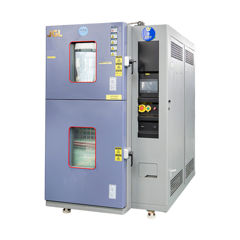
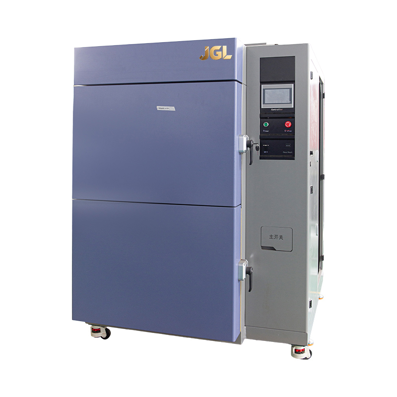
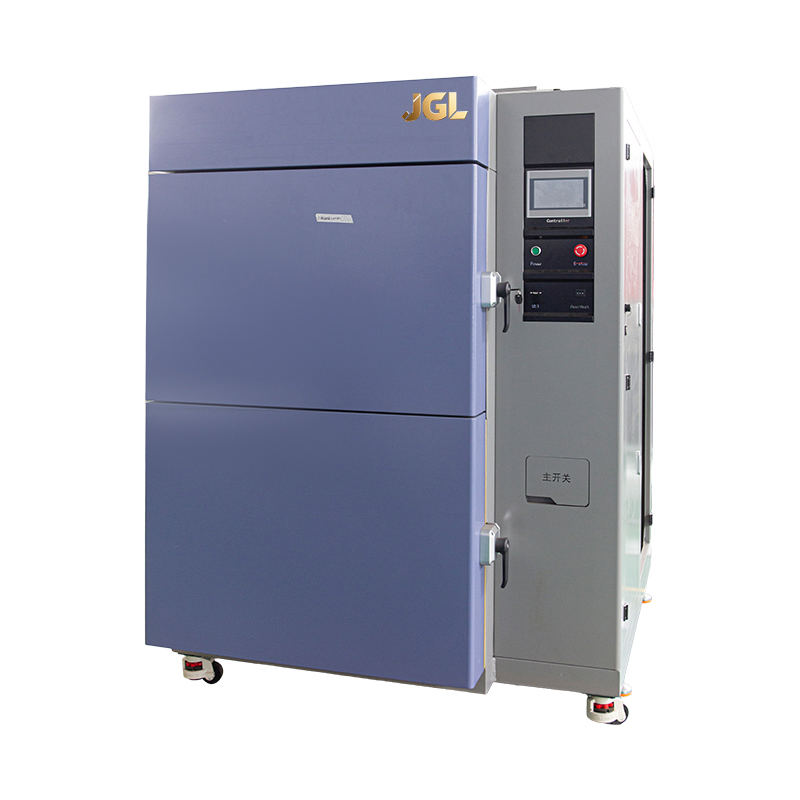
A two-section thermal shock test chamber maintains two separately conditioned zones, one held at an extreme low temperature and one held at an extreme high temperature, within a single housing. A basket carrying the test load transfers between the two zones in a matter of seconds, exposing components to a near step change in temperature rather than a gradual ramp.
How the Transfer Mechanism Works
A motorized elevator or sliding basket moves the load vertically or horizontally between zones. Transfer time is typically specified in seconds, and the goal is to minimize the transitional dwell so that the temperature change experienced by the test article approximates a true shock rather than a fast ramp. Insulated doors and rapid recovery heating and cooling systems keep each zone stable even as ambient air is exchanged during the transfer.
Where Basket Transfer Testing Fits Best
| Application | Reason for Two-Zone Method |
|---|---|
| Sealed connector and enclosure validation | Reveals seal failure under sudden pressure differential from rapid air expansion and contraction |
| Ceramic and hybrid packaging | Exposes brittle cracking that slow ramps would not trigger within a reasonable test duration |
| Military and defense qualification | Many legacy specifications call explicitly for basket transfer style shock testing |
| Coating and conformal layer adhesion | Sudden expansion mismatch separates poorly bonded layers quickly |
Single-Chamber Cycling With a High and Low Temperature Test Chamber
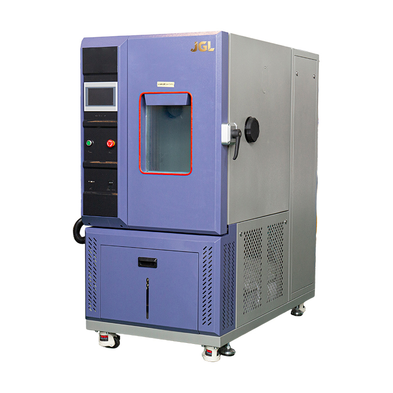
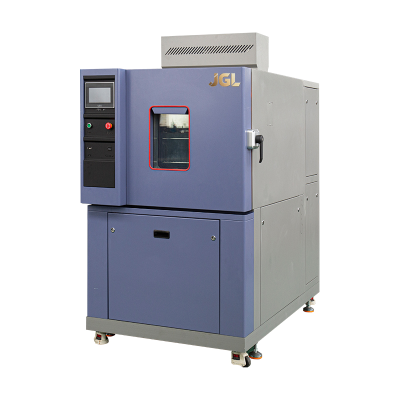
A high and low temperature test chamber takes a different approach. Rather than moving the load between zones, the chamber itself ramps its internal air temperature up and down at a programmable rate, holding the load stationary throughout the test. This design gives engineers direct control over ramp rate, dwell time, and humidity conditioning within a single controlled volume.
Why Programmability Matters
Because the ramp rate is set by the control system rather than fixed by a mechanical transfer, a single chamber can reproduce a wide range of profiles, from a gentle diurnal cycle to an aggressive stepped ramp, without changing hardware. This flexibility makes it the preferred tool when a test standard calls for a specific, documented ramp rate rather than the fastest achievable transition.
1 to 5deg C per minute typical standard ramp range
10 to 30+deg C per minute high-performance ramp range
Singlechamber volume, no physical transfer required
Comparing the Two Chamber Architectures
| Factor | Two-Section Shock Chamber | High and Low Temperature Chamber |
|---|---|---|
| Transition speed | Near instant, seconds | Programmable, minutes |
| Stress mode emphasized | Sudden shock, brittle cracking | Gradual fatigue, creep, grain growth |
| Ramp rate control | Fixed by transfer speed | Fully adjustable |
| Typical standards referenced | Shock-specific military and industrial specs | Standard cycling and endurance specs |
| Best suited to | Sealed housings, brittle materials, packaging integrity | Solder joint fatigue life, general product qualification |
In many qualification programs, both methods are used together. A product may first undergo pcb thermal cycling test work in a single chamber to establish a baseline fatigue life curve, then undergo two-zone shock testing to confirm it survives worst-case sudden transitions that fall outside the normal mission profile.
Applying Thermal Testing Across Industries
Semiconductor and Component Level Testing
thermal cycling test semiconductor programs focus heavily on die attach and wire bond integrity. Repeated expansion and contraction between the silicon die, the substrate, and the package body creates shear stress at every bonded interface. Because these interfaces are microscopic, even a small mismatch in expansion behavior between materials can accumulate into measurable resistance drift or open circuits after a defined number of cycles.
Printed Circuit Board Assemblies
A pcb thermal cycling test targets a different scale of the same problem. Surface mount solder joints connect components with very different expansion behavior to a board substrate. Repeated cycling fatigues the solder microstructure, gradually growing microcracks at the joint fillet until electrical continuity is lost. Board designers use cycling results to validate component placement, solder alloy selection, and underfill strategies before committing to volume production.
Aerospace and Defense Environments
aerospace thermal shock testing reproduces conditions that ground-based electronics rarely encounter, such as an aircraft climbing rapidly from a warm runway environment into extreme cold at altitude within minutes. An aerospace thermal shock test chamber used for this purpose must demonstrate very tight temperature uniformity and fast recovery time, since the test is only valid if the entire load reaches the target condition quickly and consistently across every point in the chamber, not just at the sensor location.
General Purpose Reliability Screening
Beyond these specific industries, a general purpose cycling chamber is used across consumer electronics, automotive electronics, industrial controls, and lighting products for burn-in and accelerated life testing, often as part of a broader environmental qualification plan that also includes humidity, vibration, and altitude testing.
Visualizing a Typical Cycling Test Flow
Each pass through the high and low temperature stages, or through the two physical zones in a shock chamber, counts as one cycle. Test plans typically define a target number of cycles, then remove samples at intervals for electrical continuity checks and cross section analysis to trace fatigue crack growth over time.
Frequently Asked Questions
Q1: What is the difference between thermal shock and temperature cycling?
Thermal shock refers to a near instant temperature transition, typically achieved by moving a load between two conditioned zones. Temperature cycling refers to a controlled ramp within a single chamber, where the rate of change is programmable rather than fixed by a physical transfer.
Q2: How many cycles are typically required for solder joint qualification?
Cycle counts vary widely depending on the applicable standard and the expected service environment, ranging from a few hundred cycles for consumer products to several thousand for automotive or aerospace grade assemblies. The exact number should be defined by the governing test specification rather than a fixed industry rule.
Q3: Does a faster ramp rate always produce a more severe test?
Not necessarily. A faster ramp increases stress concentration at rigid joints and interfaces, which can accelerate certain failure modes, but it does not proportionally accelerate mechanisms like slow creep or corrosion that depend on extended dwell time at a given temperature.
Q4: Can the same chamber perform both humidity and thermal cycling tests?
Many single chamber designs integrate humidity control alongside temperature cycling, allowing combined thermal and humidity profiles. Two-section shock chambers are generally dedicated to temperature transition testing without humidity control, since the physical transfer process is not compatible with maintaining stable humidity levels.
Q5: How is chamber uniformity verified before running a qualification test?
Uniformity is typically verified using multiple calibrated temperature sensors placed throughout the working volume, confirming that all points reach and hold the target temperature within a specified tolerance before the load itself is subjected to formal testing.
PREV:How Electrical Safety Testing Protects Semiconductor and PCB Integrity Across the Production Lifecycle
NEXT:How MIL-STD-810 Environmental Test Chambers Turn Climatic Stress Into a Reliability Signal
NEXT:How MIL-STD-810 Environmental Test Chambers Turn Climatic Stress Into a Reliability Signal
Interested in cooperation or have questions?
Featured Products
Related products
Quick Link
Contact Information
- Tel: +86-13861043568
- E-mail: 1840784112@qq.com
- Add: Tianting District, Changzhou City, Jiangsu Province, China, No. 6 Hecircuit
Scan Code
Copyright © JIANGSU BAISHENG INDUSTRIAL CO., LTD.
All Rights Reserved. Privacy Custom Precision Laboratory Testing Equipment Manufacturers
