 English
 Español
NEWS
NEWS
NEWS
NEWS
NEWS
NEWS
NEWS
NEWS
NEWS
NEWS
NEWS
NEWS
NEWS
NEWS
NEWS
NEWS

Industry News
Home / News / Industry News / How Electrical Safety Testing Protects Semiconductor and PCB Integrity Across the Production Lifecycle
How Electrical Safety Testing Protects Semiconductor and PCB Integrity Across the Production Lifecycle
Content
- 1 Why Electrical Integrity Checks Decide Whether Semiconductors and PCBs Survive the Field
- 2 The Core Instrument Categories on a Modern Test Bench
- 3 Dielectric Withstand Testing and the Electrical Safety Tester
- 4 Impedance Spectroscopy and the Precision Impedance Analyzer
- 5 Semiconductor Device Testing Under AEC-Q101 Qualification
- 6 UL 1703 and Electrical Safety in Photovoltaic-Adjacent Assemblies
- 7 Building an End-to-End Electrical Test Workflow
- 8 Common Failure Modes and How Test Data Points to Root Cause
- 9 Frequently Asked Questions
- 9.0.1 Q1: What is the difference between a hipot test and an insulation resistance test?
- 9.0.2 Q2: How often should an electrical safety tester be calibrated?
- 9.0.3 Q3: Why does impedance testing matter for a PCB that already passed continuity testing?
- 9.0.4 Q4: Does passing AEC-Q101 qualification mean every production unit is automatically compliant?
- 9.0.5 Q5: Can a single test station cover both general dielectric testing and UL 1703 specific profiles?
- 9.0.6 Q6: What is the most common mistake in setting up a dielectric withstand test?
Why Electrical Integrity Checks Decide Whether Semiconductors and PCBs Survive the Field
A single leakage path across an insulation barrier or a shifted impedance value on a differential trace rarely shows up on a visual inspection line. It shows up months later, in a warranty claim, a field failure report, or a recall. Manufacturers producing semiconductor components and printed circuit boards for automotive, industrial, and renewable energy markets have learned that the difference between a reliable product and a costly failure is almost always found in the electrical test data, not the physical dimensions.
Modern production floors rely on a coordinated set of electronic test instruments to catch these issues before parts leave the facility. These instruments span dielectric withstand testers, impedance analyzers, and device-level functional testers, each targeting a different failure mechanism. Understanding how they fit together, and which standards govern their use, is the foundation of a defensible quality program.
The stakes differ by application. A consumer accessory that fails electrically might generate a return. An automotive power module or a rooftop solar combiner box that fails electrically can generate a safety incident, a liability claim, or a regulatory inquiry. That difference in consequence is exactly why standards bodies wrote detailed qualification frameworks such as AEC-Q101 for automotive-grade discrete semiconductors and UL 1703 for photovoltaic module electronics, and why production teams building for those markets cannot treat electrical testing as an optional final gate.
What makes this discipline harder than it looks is that electrical defects are rarely binary. A barrier does not simply work or fail; it degrades along a continuum, and a unit that passes today under nominal conditions can fail tomorrow under a slightly elevated humidity load or a marginally higher line voltage. Building test programs that account for that continuum, rather than treating every pass as a permanent guarantee, is the mindset shift this article works through.
The Core Instrument Categories on a Modern Test Bench
Before diving into specific test methods, it helps to separate the instrument categories by what physical property they measure and where in the process they typically appear.
| Instrument Category | Primary Measurement | Typical Process Stage |
|---|---|---|
| Electrical safety tester | Leakage current, dielectric withstand, insulation resistance | Final assembly, incoming inspection |
| Precision impedance analyzer | Impedance magnitude and phase across frequency | Component qualification, material characterization |
| Semiconductor device tester | Electrical parametrics, functional response | Wafer sort, final test, burn-in |
Each category answers a different question. The safety tester asks whether a barrier will hold under stress. The impedance analyzer asks how a component behaves across a frequency band. The device tester asks whether the finished part performs to its published specification. Treating these as separate but linked disciplines, rather than one generic bucket labeled testing, is what allows a quality team to build a workflow that catches failures at the cheapest possible stage.
Instrument selection also depends on production volume and the acceptable cycle time per unit. A high-volume line producing thousands of assemblies per shift generally favors automated, fixture-based safety testers with programmable test sequences and pass or fail output feeding directly into a manufacturing execution system. A lower-volume line qualifying new designs or running engineering samples benefits more from a manually operated bench instrument with finer control over ramp rates, dwell times, and data logging resolution, since the goal there is characterization rather than throughput.
Matching Instrument Capability to Application Risk
Not every board needs the same depth of electrical scrutiny. A low-voltage signal board operating well below any hazardous voltage threshold may only need a basic insulation resistance check. A board switching mains voltage, driving a motor, or sitting inside a sealed outdoor enclosure warrants the full sequence of hipot, insulation resistance, and ground bond testing, often supplemented with impedance characterization on any high-speed signal layers. Matching the depth of testing to the actual risk profile of the assembly keeps cycle times reasonable without leaving genuine hazards unchecked.
Dielectric Withstand Testing and the Electrical Safety Tester
Dielectric withstand testing, sometimes called hipot testing, applies a controlled high voltage across an insulation barrier and monitors leakage current. If the barrier is compromised by a manufacturing defect such as a thin spot in conformal coating, a contaminated creepage path, or a nicked wire insulation layer, the leakage current rises above the programmed threshold and the unit fails before it ever reaches a customer.
An electrical safety tester typically runs three related tests in sequence during a production line cycle:
- AC or DC hipot testing, applying elevated voltage for a fixed dwell time to confirm the insulation barrier does not break down
- Insulation resistance testing, applying a lower DC voltage to measure the resistance of the barrier in ohms
- Ground bond testing, verifying the continuity and low impedance of the protective earth connection on enclosed assemblies
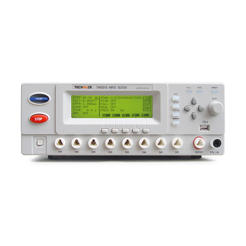
In practice, test parameters are not arbitrary. They trace back to the working voltage of the assembly and the required creepage and clearance distances for its intended environment. A board destined for a damp indoor enclosure carries different dwell time and voltage requirements than one destined for an outdoor rooftop mount exposed to condensation and UV cycling. Programming the safety tester with the correct voltage ramp rate also matters: a ramp that is too fast can produce nuisance trips on units that would otherwise pass, while a ramp that is too slow extends cycle time without adding meaningful detection value.
A properly maintained insulation barrier should show leakage current in the microamp range under rated test voltage. A reading that creeps upward across a production lot, even while still under the pass threshold, is often the earliest warning sign of a drifting coating or lamination process upstream.
Fixture Design and Repeatability
The test fixture connecting the safety tester to the unit under test matters as much as the instrument itself. Poor probe contact, worn spring pins, or inconsistent clamping pressure can introduce measurement noise that either masks a real defect or produces a nuisance failure on a good unit. Fixtures used for dielectric withstand testing should be inspected on a scheduled interval, with probe resistance verified against a known reference load, since a degraded fixture can silently erode the confidence level of every test result it produces without ever triggering an obvious alarm.
Environmental conditions around the test station also influence repeatability. Relative humidity above typical indoor ranges can lower surface insulation resistance readings independent of any actual defect in the unit, which is why many test procedures specify an acceptable humidity band for the test environment itself, not just for the product being tested.
Impedance Spectroscopy and the Precision Impedance Analyzer
Where the safety tester answers a pass or fail question about insulation, the precision impedance analyzer answers a much richer question: how does a component or material behave across a range of frequencies. This is impedance spectroscopy, and it is central to characterizing passive components, connector interfaces, battery cells, and the dielectric materials used inside multilayer PCBs.
A sweep typically covers several decades of frequency, plotting both magnitude and phase angle. The resulting curve reveals information a single-point measurement cannot:
- Resonant frequency shifts that indicate parasitic inductance or capacitance in a component package
- Dielectric loss tangent changes that signal moisture ingress or thermal degradation in a laminate
- Contact resistance instability at connector or via interfaces under repeated cycling
Interpreting a Frequency Sweep in Practice
Engineers reviewing a Bode-style plot from an impedance sweep are usually looking for two things: does the curve match the reference profile from a known-good sample, and does the phase angle cross zero at the frequency the design predicts. A shifted crossover point often points to a subtle change in copper trace geometry or dielectric thickness that dimensional inspection alone would miss entirely.
4Decades of frequency typically swept in a standard characterization run
2Core outputs per data point: magnitude and phase
1Reference sample needed to build a pass or fail correlation model
Building a Correlation Model from Sweep Data
Raw impedance curves are only useful once they are converted into a pass or fail decision that a production line can act on quickly. The common approach is to collect sweep data from a statistically sound sample of known-good units, establish an acceptable envelope around the average curve at each frequency point, and then flag any production unit whose sweep exits that envelope at any point along the frequency range. This envelope approach catches subtle shifts that a single-frequency spot check would miss, while still producing a fast automated pass or fail result rather than requiring an engineer to manually review every curve.
Material characterization work extends this same technique to incoming laminate and prepreg lots. Because dielectric constant and loss tangent both vary with frequency, a supplier claiming a single-point specification value does not tell the full story. Running an incoming lot through a frequency sweep and comparing it against the qualified baseline curve is a more reliable way to catch a material substitution or a formulation change before it reaches a finished board.
Semiconductor Device Testing Under AEC-Q101 Qualification
Discrete semiconductor components used in automotive applications, including diodes, transistors, and power modules, are typically qualified against AEC-Q101, a stress test qualification standard developed by the automotive electronics council. Passing AEC-Q101 does not certify a single unit; it certifies that a specific design and process combination reliably meets defined stress limits across temperature cycling, humidity, electrical overstress, and mechanical shock.
A semiconductor device tester supports this qualification effort in two distinct ways. During the qualification build itself, it captures baseline parametric data such as threshold voltage, leakage current, and switching characteristics before and after each stress step, so engineers can quantify any parametric drift. During ongoing production, the same tester, or a production-configured variant, screens every unit against the qualified parametric window, ensuring the process stays inside the envelope that was originally proven out.
Parametric Categories Commonly Screened
| Parameter Group | What It Detects |
|---|---|
| Static electrical parameters | Threshold shifts, leakage current outside design window |
| Dynamic switching behavior | Rise and fall time drift, timing skew under load |
| Thermal response | Junction temperature behavior under sustained current |
Because automotive-grade parts often carry a longer expected service life and operate across a wider temperature range than consumer-grade equivalents, the device tester program for AEC-Q101 qualification generally includes more temperature corners and a tighter statistical sampling plan than a comparable consumer part would require.
Burn-In and Its Role in Screening Latent Defects
Some failure mechanisms only surface after a period of electrical and thermal stress, which is why many qualification and high-reliability production programs include a burn-in step ahead of final device testing. Units are operated under elevated temperature and biased voltage for a defined duration, then re-tested against the original parametric window. A unit that drifts outside acceptable limits after burn-in, even though it passed the same test before burn-in, is flagged as carrying a latent defect that would likely have caused an early field failure. This screening step is particularly valuable for automotive and industrial applications where an early-life failure is far more costly to remediate than a slightly longer test cycle at the factory.
UL 1703 and Electrical Safety in Photovoltaic-Adjacent Assemblies
UL 1703 is a safety standard covering flat-plate photovoltaic modules and panels, and it directly shapes the dielectric and grounding test requirements for any PCB or electronic assembly integrated into a module junction box, combiner, or module-level power electronics unit. Because these assemblies are mounted outdoors and exposed to weather cycling, UV exposure, and long service intervals with limited maintenance access, the standard sets a higher bar for insulation integrity than most indoor electronics.
Assemblies evaluated under this framework are typically subjected to:
- Wet insulation resistance testing, simulating condensation or rain exposure on the enclosure
- Extended dielectric withstand dwell times reflecting the outdoor working voltage class
- Ground continuity verification across the full current path, including any bonded frame or mounting hardware
Because these tests overlap closely with the dielectric withstand and insulation resistance functions of a general purpose electrical safety tester, many production lines building module-level electronics or combiner box assemblies configure their safety test station with UL 1703 specific voltage and dwell time profiles as a selectable test recipe, rather than maintaining a separate dedicated instrument.
Long-term field exposure also introduces a consideration that indoor electronics rarely face: thermal cycling combined with UV exposure can gradually embrittle potting compounds and gasket materials around cable entries, opening a slow moisture ingress path that would not be present on the day the unit shipped. For this reason, some module electronics programs supplement initial UL 1703 qualification testing with periodic sample pulls from the field or from accelerated weathering chambers, re-running the same dielectric and ground bond sequence to confirm the barrier is holding up over the module's rated service life rather than only at time zero.
Building an End-to-End Electrical Test Workflow
Individually, each instrument category catches a different class of defect. Sequenced correctly across the production flow, they form a layered defense that catches problems at the earliest and cheapest point possible.
The sequence above is deliberately ordered from least to most costly to remediate. A dielectric defect caught at incoming material inspection costs the price of a component. The same defect caught after final assembly costs the labor of the entire build. Caught after shipment, it costs a field service call and a reputation hit. This is the economic argument for investing in test coverage at every stage rather than relying on a single end-of-line gate.
Data Traceability Across Stages
A workflow is only as strong as its record keeping. Each test stage should log the instrument identifier, calibration status, test recipe version, and pass or fail result against a unit serial number. This traceability chain is what allows a quality team to trace a field failure back to a specific production lot, shift, or even a specific test fixture, rather than guessing at root cause after the fact.
Setting Realistic Sampling Plans
Not every stage in the workflow needs one hundred percent inspection, and treating all stages equally often wastes cycle time better spent elsewhere. Incoming material characterization is commonly performed on a statistical sample per lot, since material properties tend to be consistent within a single production batch from a qualified supplier. Final assembly safety testing, by contrast, is typically run at one hundred percent coverage, because it is checking the finished barrier that the end customer will actually depend on, and the cost of a missed unit at that stage is far higher than the cost of an extra few seconds of test time.
| Process Stage | Typical Coverage |
|---|---|
| Incoming material characterization | Statistical sample per lot |
| Sub-assembly insulation check | Statistical sample or one hundred percent, risk dependent |
| Final assembly safety test | One hundred percent |
| Device qualification parametric screen | One hundred percent during qualification build |
Common Failure Modes and How Test Data Points to Root Cause
Reading test failures correctly is as important as generating them. The table below summarizes patterns that experienced test engineers watch for.
| Observed Signal | Likely Root Cause |
|---|---|
| Leakage current rising gradually across a lot | Coating thickness drift or contamination on the applicator |
| Impedance phase crossover shifted higher in frequency | Thinner dielectric layer or altered trace geometry |
| Ground bond resistance intermittent across units | Loose fastener torque or inconsistent bonding surface prep |
| Parametric drift concentrated in one temperature corner | Localized thermal stress during a specific process step |
Investigating these patterns generally works backward through the process flow, comparing the test data against upstream process logs such as coating line temperature, lamination press parameters, or reflow profiles. In most cases, the electrical test data narrows the search to a specific process step long before a physical failure analysis would.
Statistical process control charts built directly from test instrument output make these patterns visible before they turn into hard failures. Plotting leakage current, insulation resistance, or key impedance parameters over time, rather than only recording a binary pass or fail, gives engineers an early warning system that flags a process moving out of its normal band while every individual unit is still technically passing. Waiting for the first hard failure to investigate a process shift almost always means a number of marginal units already left the facility before the trend became obvious.
Frequently Asked Questions
Q1: What is the difference between a hipot test and an insulation resistance test?
A hipot test applies a higher voltage for a short dwell time and looks for a dielectric breakdown event or excessive leakage current. An insulation resistance test applies a lower, steady DC voltage and calculates a resistance value in ohms, giving a more granular picture of barrier quality even when the unit is nowhere near breakdown.
Q2: How often should an electrical safety tester be calibrated?
Most quality programs calibrate safety testers on an annual cycle at minimum, with additional verification checks after any firmware update, fixture change, or significant maintenance event, since even a small voltage measurement drift can shift pass and fail boundaries across an entire production run.
Q3: Why does impedance testing matter for a PCB that already passed continuity testing?
Continuity testing confirms a connection exists; it says nothing about how that connection behaves under signal frequency. A trace can be fully continuous and still present an impedance mismatch that causes reflections, timing errors, or excess loss at operating frequency, which only a frequency sweep can reveal.
Q4: Does passing AEC-Q101 qualification mean every production unit is automatically compliant?
No. Qualification proves the design and process combination is capable of meeting the standard under defined stress conditions. Ongoing production still requires ongoing parametric screening to confirm the process has not drifted outside the qualified window.
Q5: Can a single test station cover both general dielectric testing and UL 1703 specific profiles?
Yes, in most cases. Because the underlying measurement, applied voltage and leakage current, is the same physical test, a safety tester with selectable voltage, dwell time, and wet condition recipes can support both general purpose testing and the extended profiles required for outdoor photovoltaic-adjacent assemblies.
Q6: What is the most common mistake in setting up a dielectric withstand test?
Programming a voltage ramp rate that does not match the assembly under test is the most frequent setup error. A ramp that is too aggressive can trigger nuisance trips on healthy units, while a ramp that is too slow adds unnecessary cycle time without improving defect detection.
PREV:ISO 16750 & IEC 60068: Automotive Environmental Testing
NEXT:How Two-Zone Thermal Shock Testing Exposes Solder Joint Fatigue That Slow Ramp Cycling Misses
NEXT:How Two-Zone Thermal Shock Testing Exposes Solder Joint Fatigue That Slow Ramp Cycling Misses
Interested in cooperation or have questions?
Featured Products
Related products
Quick Link
Contact Information
- Tel: +86-13861043568
- E-mail: 1840784112@qq.com
- Add: Tianting District, Changzhou City, Jiangsu Province, China, No. 6 Hecircuit
Scan Code
Copyright © JIANGSU BAISHENG INDUSTRIAL CO., LTD.
All Rights Reserved. Privacy Custom Precision Laboratory Testing Equipment Manufacturers
